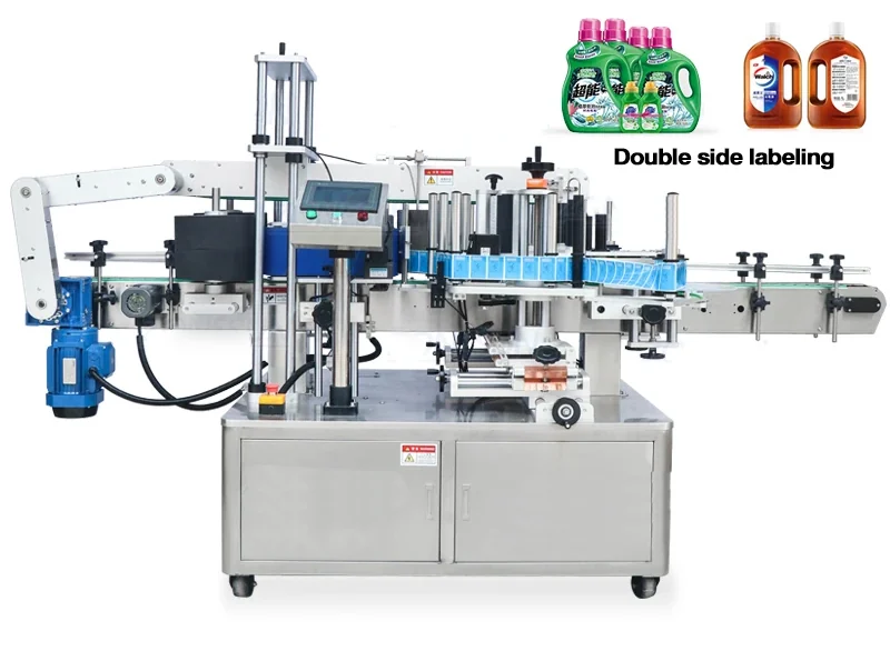
How to plan labelling line layout and product flow
A labeller needs more than a clear space on a drawing. Product spacing, stability, conveyor handovers, accumulation and restart behaviour must be planned as one flow so the label is applied to a controlled pack rather than a moving problem.
What makes a labelling line layout work reliably?
A reliable labelling line gives every product a known position, speed and orientation before the label is dispensed, then provides enough controlled outfeed for wipe-down, inspection and recovery. The layout must account for product spacing, unstable containers, upstream surges, downstream stops, operator access and the exact point at which each machine owns the product.
The labeller should therefore be positioned from a process map rather than added to the remaining floor space. A short layout review before quotation can expose missing spacing devices, unsupported conveyor gaps, inaccessible label rolls and reject locations that cannot handle a failed product safely.
Map the complete product journey
Start with the product in the condition it reaches the labeller. Record whether it is empty or filled, capped, warm, cold, wet, flexible, top-heavy or prone to sliding. Then trace the product through infeed, spacing, sensing, label application, wipe-down or wrap, coding, inspection, reject and outfeed. Each stage should have an owner and an observable result.
A simple process map should show the direction of travel, conveyor datum, product pitch, label position, sensor locations, operator side, guard access, roll-change space and the connection to surrounding machines. Where a filler or capper discharges products in groups, the layout must describe how those groups become the repeatable pitch needed by the labeller.
Create repeatable product spacing
Automatic labelling depends on a gap between products. The gap allows a sensor to identify each pack and gives the label head time to complete one application before the next trigger. The correct spacing method depends on the product and line behaviour: side belts can both separate and stabilise some packs, a spacing wheel can suit repeatable rigid containers, and a screw or positive infeed may be appropriate when accurate pitch is required. The selection is application-specific and should be proven with samples.
Do not use an average gap as the only design input. Check the minimum gap during upstream surges, the effect of downstream backpressure and the way a stopped product restarts. Two products touching briefly can create one long sensor signal, an incorrect label trigger or a double application.
Stabilise the pack before the label is presented
Side guides alone may be enough for a rigid, square product, but soft bottles, oval packs, tall containers, pouches and lightweight cartons may need additional control. Options can include top-hold belts, side stabilising belts, orientation devices, nests or a transfer that supports the product across a gap. The control should not deform the pack or cover the label area.
Measure the actual base, body and cap rather than using nominal volume. A container can share the same stated capacity as another SKU yet have a different centre of gravity, shoulder profile or moulding seam. These differences determine guide contact and the available reference surface.
Plan accumulation and conveyor handovers
Accumulation provides time for short interruptions, but uncontrolled backpressure can move products sideways or force them into the labelling station. Decide where accumulation is allowed, how much is useful and which machine stops first when the buffer is full. The upstream and downstream control states should match the physical capacity of the conveyors.
Check every transfer plate and conveyor gap with the smallest, lightest and least stable product. A pack that tips at a handover will never reach the label head repeatably. For top-and-bottom labelling, the underside application area needs a deliberately supported transfer rather than an ordinary conveyor joint.
Locate coding, inspection and reject functions
Where a coder, vision sensor or barcode reader is included, the layout must give it a clear view and enough product control to make the result meaningful. A reader positioned while the label is still moving or before final wipe-down may inspect a condition that changes later. A reject device needs confirmed product tracking from inspection to removal and a destination that can safely contain the rejected pack.
For print-and-apply systems, separate the data check, print check, label-present check and applied-label check. These are different controls and may require different sensors. The print-and-apply barcode verification guide explains how to define the evidence.
Protect access and maintenance space
Leave practical room to load label rolls, thread the web, clean sensors, remove a jam and isolate equipment. Guarding and access arrangements require a site-specific risk assessment. HSE guidance explains that access to dangerous parts should be prevented or dangerous movement stopped before a person enters the danger zone; the final safety design must be completed by competent people for the actual line.
Useful reference: HSE equipment and machinery guidance. This general link does not replace the project risk assessment, PUWER duties or the machine supplier's instructions.
Information for a useful layout review
- Scaled line layout with travel direction, conveyor heights and operator side.
- Smallest and largest products, filled weights and representative samples.
- Normal and maximum production rates, including batch and surge behaviour.
- Upstream and downstream machine states, stop logic and available accumulation.
- Label position, roll data, coding, inspection and reject requirements.
- Utility locations, guard access, cleaning space and maintenance routes.
Continue the integration work
Review the labeller within the complete line
Send a layout, product samples, line rates and surrounding-machine details so Lancing can identify the handling and control scope around the label head.